A transformer is a static device used to convert voltage and current from one system to another at a specific frequency. The performance of a transformer depends on the correct connection and phase relationship between its primary and secondary windings. Polarity and Phase Relation Test is an important test of a transformer, which determines the phase difference and correct polarity between the primary and secondary windings.
This test determines how the two windings of the transformer are in phase with each other and what their polarity (dot convention) is – whether they are in the same direction or opposite. This information is especially important when multiple transformers are used in parallel connection, because if the polarity or phase does not match, a large current flow can damage the circuit or transformer.
What is the Polarity and Phase Relationship test?
Transformer Polarity and Phase Relationship Test is an electrical test that determines the polarity and phase relationship of the voltage between the primary and secondary windings of a transformer. The main purpose of this test is to ensure that the transformers are properly connected, especially when multiple transformers are operated in parallel.
- This test determines:
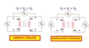
Whether the voltage in the primary and secondary windings is flowing in the same direction (Additive polarity) or the opposite direction (Subtractive polarity). - Whether the phase shift is correct and whether the phase relationship is correct:
If the polarity and phase relationship are not correct, the transformer may experience short circuits, overloads, or power losses. Therefore, this test is very important before installing the transformer.
What is the polarity of a transformer?
The polarity of a transformer refers to the relative direction or phase relationship of the terminals of the primary and secondary windings. Simply put, it determines whether the input and output voltages of a transformer are in phase with each other or in opposite phase.
There are two types of polarity:
- Additive Polarity: where the primary and secondary voltages add to each other.
- Subtractive Polarity: where the primary and secondary voltages subtract from each other.
Knowing the polarity is important because:
- Transformers must have the same polarity to be connected in parallel.
- Connecting the wrong polarity can cause a short circuit and damage the system.
- Polarity is usually determined by testing and is indicated by the terminal markings on the transformer.
Polarity Test Equipment
Polarity Test Procedure is a method of testing the polarity of an electrical circuit or connection. This test is commonly used in DC (Direct Current) systems, where it is very important to determine the polarity correctly. Here is a description of a polarity test procedure.
Polarity Test Method:
Instrument:
- Multimeter (Digital or Analog)
- Test Leads
- Power Supply
Steps:
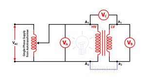
Prepare the instrument: Prepare the multimeter and confirm the settings. Set the multimeter to test DC voltage. Connect the test leads to the correct ports of the multimeter (red lead to the +V port and black lead to the -V port).
Check the power supply: Turn on the power supply of the circuit or device under test and confirm the correct voltage.
Check the polarity: Connect the multimeter to the positive (+) pole of the circuit and connect the other test lead to the negative (-) pole.
If the multimeter display shows positive voltage (e.g., 12V, 5V), then the polarity is correct.
If the display shows negative voltage (e.g., 1-12V 5-5V, then the polarity is reversed.
If the polarity is reversed: If the polarity is reversed, review the circuit connections and re-establish the correct connection of the positive and negative poles.
Final Check: Turn off the circuit or device after everything is connected properly and testing is complete. Check the polarity again for correctness.
Warning:
- Never try to connect the wrong polarity, especially for electrical appliances, as this can be dangerous.
- Do not test if the circuit is not powered.
- Use proper care when using a multimeter and keep the equipment connected properly.
- By following this procedure, you can easily and safely test polarity.
What is the Transformer Phase Relation Test?
Transformer phase relationship is the phase relationship of the electrical wave between the primary and secondary windings of a transformer. It affects the performance of the transformer and the nature of the output voltage.
When a changing electrical power is applied to the primary circuit of a transformer, it is reflected in the secondary circuit. Phase relationship refers to the speed and phase difference of the voltage between the primary and secondary circuits.
In general, the phase relationship of a transformer depends on several factors, such as:
- Connection type of transformer: If it is a Delta-Wye connection or any other type of connection, then the phase relationship may vary.
- Polarity of primary and secondary windings: The polarity of the windings of the transformer affects the phase relationship. Proper polarity should be ensured, so that the correct output voltage and phase relationship can be ensured.
For example, if the primary winding of a transformer is at 0° phase, the phase relationship of the secondary winding will depend on this configuration. This can be ±180° or other different values, depending on the polarity and connections.
Phase Relation Test Steps
Phase Relation Test is a test method used to check the phase relationship between systems, usually in electronic circuits or signal processing. Here are the steps of a common phase relation test in Bengali:
Required Equipment:
Transformer Phase Relation Test is an important test, which is mainly done to verify whether the phase relation or phase difference of the transformer is correct or not. The equipment required for this in Bengali or “Test Requirement Equipment” is given below:
- Voltmeter: For measuring phase-to-phase and phase-to-neutral voltage.
- Multimeter: For measuring voltage, current, and resistance in different ranges.
- Phase Sequence Meter: Used to verify the phase sequence or order.
- Single-phase power supply or voltage source: To provide the required input voltage for testing.
- Connection cable and contact clips (Test leads & crocodile clips): For making connections at different points.
- Insulation gloves and safety equipment: Must be used for electrical safety.
Initial preparation Test:
- Prepare the necessary tools and equipment for the test, such as a signal generator, oscilloscope, voltmeter, or phase meter.
- Test the circuit or equipment to ensure proper signal flow.
Provide input to the system:
- Input a known sine wave into the system, whose frequency and amplitude are accurately determined.
Output signal measurement:
- Measure the output signal as well as the input signal, usually using an oscilloscope or phase meter.
Phase difference measurement:
- Measure the phase difference between the input and output signals. An oscilloscope or phase meter is used for this.
- This measurement will identify the phase shift, which indicates the relationship between the output and input signals of the system.
Phase relationship analysis:
- Analyze the phase relationship of the input and output signals. Typically, the system output is seen to be shifted relative to the input.
- The shift can be 0° (or 360°), 90°, 180°, etc.
Documenting the results:
- Document the test results accurately. This should include the phase shift of the signal and other system characteristics (such as amplitude).
Determining the phase relationship:
- If any average leakage or other abnormalities are observed in the signal, identify their cause.
- Determine the relationship of possible problems or system behavior from the phase relationship.
Ending the test:
- Perform various optional tests of the system, such as changing the input or output frequency, changing the amplitude of the signal, etc.
- After testing, properly shut down and clean all equipment.
Importance of Transformer Polarity and Phase Relationship Test
Importance of Polarity Test:
The polarity of a transformer refers to the relative direction of the voltage at the ends of the primary and secondary windings. The polarity test is very important because:
- Ensuring correct connection: If multiple transformers are connected in parallel, incorrect polarity can cause a fatal short circuit.
- In case of instrument transformer: Incorrect polarity of CT (Current Transformer) or PT (Potential Transformer) can cause incorrect readings or operation in the metering or protection system.
- Maintaining Phase: Knowing the polarity helps to understand how the primary and secondary of the transformer relate to each other, which is very important for correct phasing.
Importance of Phase Relationship Test:
Phase relationship or phase angle refers to the angular relationship between the primary and secondary voltages. Its importance is:
- System synchronization: If power is added from different sources, synchronization is not possible without a proper phase relationship.
- Loss reduction: If proper phasing is not maintained, unnecessary reactive power and load imbalance occur in the power system.
- Transformer bank phasing: In case of delta-star or star-delta connection, it is very important to know the correct phase shift so that parallel operation is done properly.